
This post describes a method to use the Raspberry Pi Codec Zero audio board with a Raspberry Pi 1 Model B Rev 2 by soldering a few wires to the P5 header of the Raspberry Pi board.
Plan
I want to record analog audio signals with my Raspberry Pi.
Because Raspberry Pi boards do not have audio input ports, I need an extension board (HAT) that provides an audio input capability. Fortunately, audio HATs are readily available. A number of these are listed in the documentation on Raspberry Pi Audio.
My project only needs Aux Input and Aux Output signals, therefore the IQaudio Codec Zero seems like a good choice. It is based on the DA7212 codec chip and uses I2S signals to transfer digital audio data between the RPi and the codec. It can play audio and record audio and do both at the same time.
I knew I had an old Raspberry Pi Model B lying around which seemed perfect for this project. It may be old and a little slower than the recent models, but I love the fact that it uses less power. I was confident that it would work. The GPIO header is compatible between all Raspberry Pi models, right?
Wrong, of course.
Problem
The 40-pin GPIO header was introduced for the Raspberry Pi 1 Model A+ and B+ (as explained on the eLinux wiki). When I found back my old RPi, it turned out to be an older Raspberry Pi 1 Model B Rev 2 with a 26-pin GPIO header.
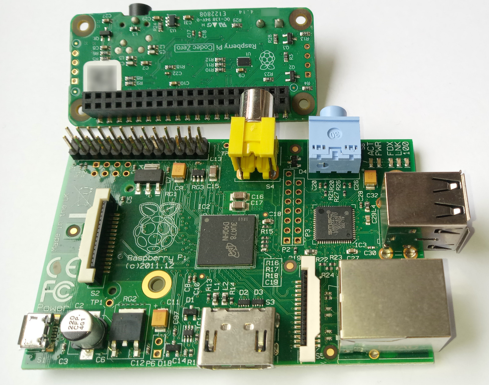
This causes a number of problems. Most obviously, the Codec Zero board physically does not fit on my RPi because the yellow composite video connector is in the way.
But even if I could somehow make the boards fit, it would still not work because the Codec Zero uses pins that simply do not exist on my RPi. The I2S bus uses 4 pins: PCM-CLK, PCM-FS, PCM-DIN and PCM-DOUT. Three of these pins are located among the lower 14 pins of the 40-pin GPIO connector.

At this point I considered ditching my old RPi and buying a new one for the project. However I really liked the idea of using the old board and I still hoped that there might be trick to make it work.
Workaround
As it turns out, my RPi has a P5 header. This header is not used often and RPi boards are shipped without pins soldered to the P5 pads. The P5 header brings out 4 additional GPIO pins. And these pins can be used as alternative pins for the I2S signal. Exactly what I need!
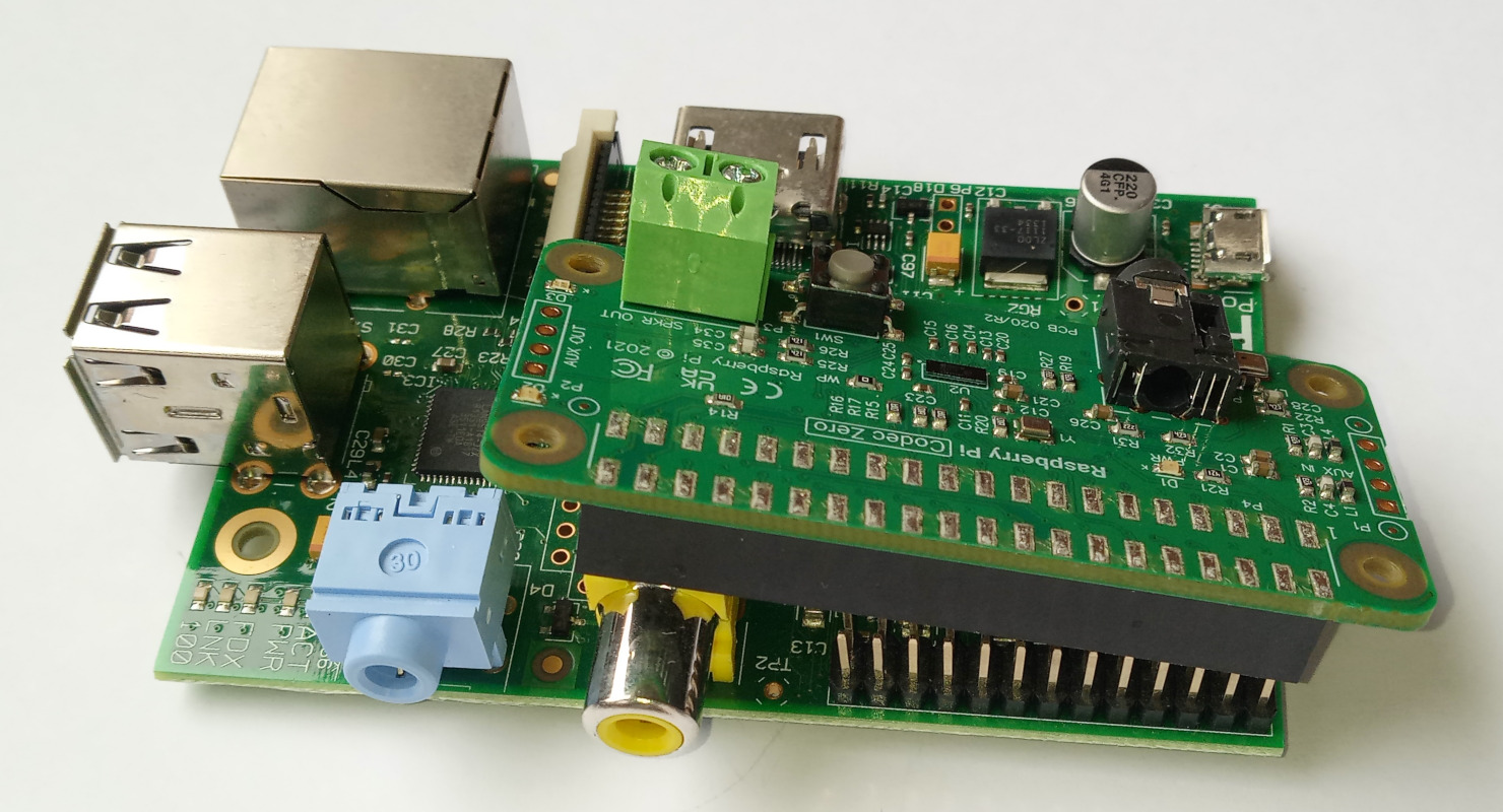
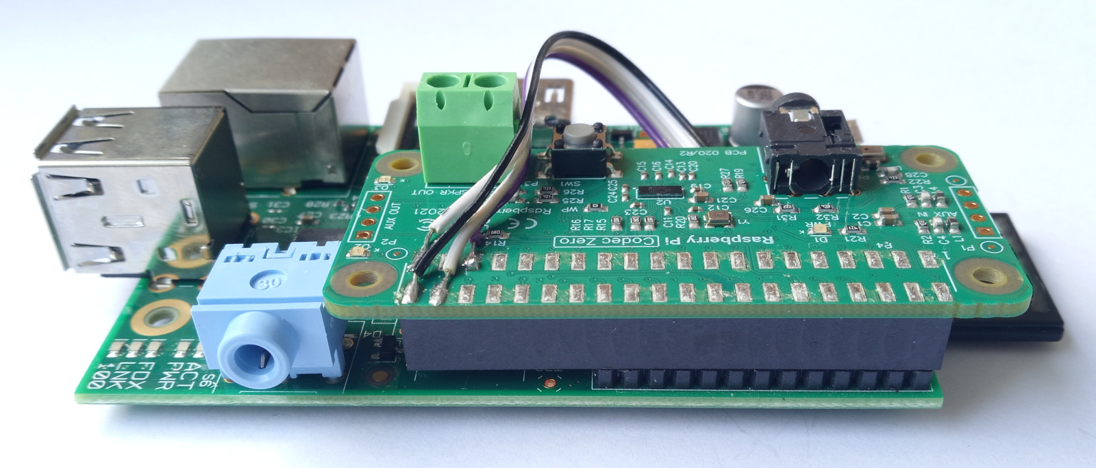
I removed the composite video connector from my RPi board to make room for the GPIO connector of the Codec Zero. At first I tried to unsolder the connector, but I don't have the right tools to do that kind of rework and I completely failed to get it loose. In the end, I just used a small wire cutter to cut the leads of the connector.
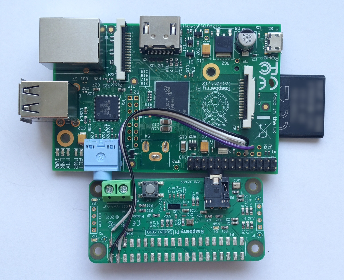
I then soldered a 4-wire ribbon cable between the P5 header and the Codec Zero board, as follows:
- P5 pin 6 (PCM-DOUT) to Codec Zero pin 40
- P5 pin 8 (ground) to Codec Zero pin 39
- P5 pin 5 (PCM-DIN) to Codec Zero pin 38
- P5 pin 4 (PCM-FS) to Codec Zero pin 35
The PCM-CLK signal is not needed because the Codec Zero is already connected to a PCM-CLK signal through GPIO18 on the 26-pin GPIO header of my RPi. The ground wire may not be strictly necessary, but it provides a return path close to the I2S data signals and may help to avoid signal integrity issues.
Configuring I2S pins
With the wires in place as described above, we now have the complete set of I2S signals connected between RPi and Codec Zero. And that is great. However, some of the signals are wired to the 26-pin GPIO header, while others are wired to the P5 header. This is probably not what the audio drivers expect. So I need to configure the RPi to tell it which pins to use for the I2S signals.
I'm running Raspberry Pi OS Trixie (previously called Raspbian).
It has a tool called pinctrl to configure GPIO pin functions.
Let's first run the tool to see the default settings:
Apparently, the OS configures my RPi by default to enable I2S signals on the P5 header. This is almost what I want, but not exactly. I want the PCM-CLK signal on GPIO18, and the other I2S signals on P5.
Let's run pinctrl commands to adjust the settings.
I configure all potential I2S pins to make sure that I get the correct configuration regardless of default settings:
Perfect!
The RPi will forget these settings when it reboots.
To make them permanent, I could create a script that runs the pinctrl commands automatically during boot.
Testing
The Codec Zero must be configured before it can be used as an audio device. This is unrelated to the changes I made in the wiring; the same steps would be necessary for a Codec Zero on a modern 40-pin RPi.
The documentation provided with the Codec Zero is not very detailed. But I found a blog post on How to get the IQaudio Codec Zero to work. It contains a lot of helpful information.
First, the RPi must be configured to load the Codec Zero audio driver during boot.
This is done by making changes in /boot/firmware/config.txt:
- Add this line to enable the Codec Zero driver:
dtoverlay=rpi-codeczero - Disable the built-in audio device of the RPi by changing the line
dtparam=audio=on
into
# dtparam=audio=on - Disable audio output via HDMI by changing the line
dtoverlay=vc4-kms-v3d
into
dtoverlay=vc4-kms-v3d,noaudio
Reboot, and test that the Codec Zero is detected:
To get an audio signal out, several mixer settings must be adjusted. I used the following commands (these will be explained later in this post):
And now, finally, it is time to play some music:
The first time I tried this, I heard nothing. And to make matters worse, I noticed a scary error in the kernel log messages:
bcm2835-i2s 20203000.i2s: I2S SYNC error!
I was worried that my trick to connect the I2S signals was not working. But it turned out that I was making other mistakes and the I2S signals were fine.
One mistake was that I got some of the mixer settings wrong. My next mistake was plugging a headphone into the jack connector on the Codec Zero, which is not a headphone connector. The 3.5mm jack is, of course, a microphone input connector. The "Headphone" signal of the Codec Zero is routed to the AUX OUT header, and the "Lineout" signal is routed to the screw terminals. These are the places where I should connect my headphones to hear the audio signal.
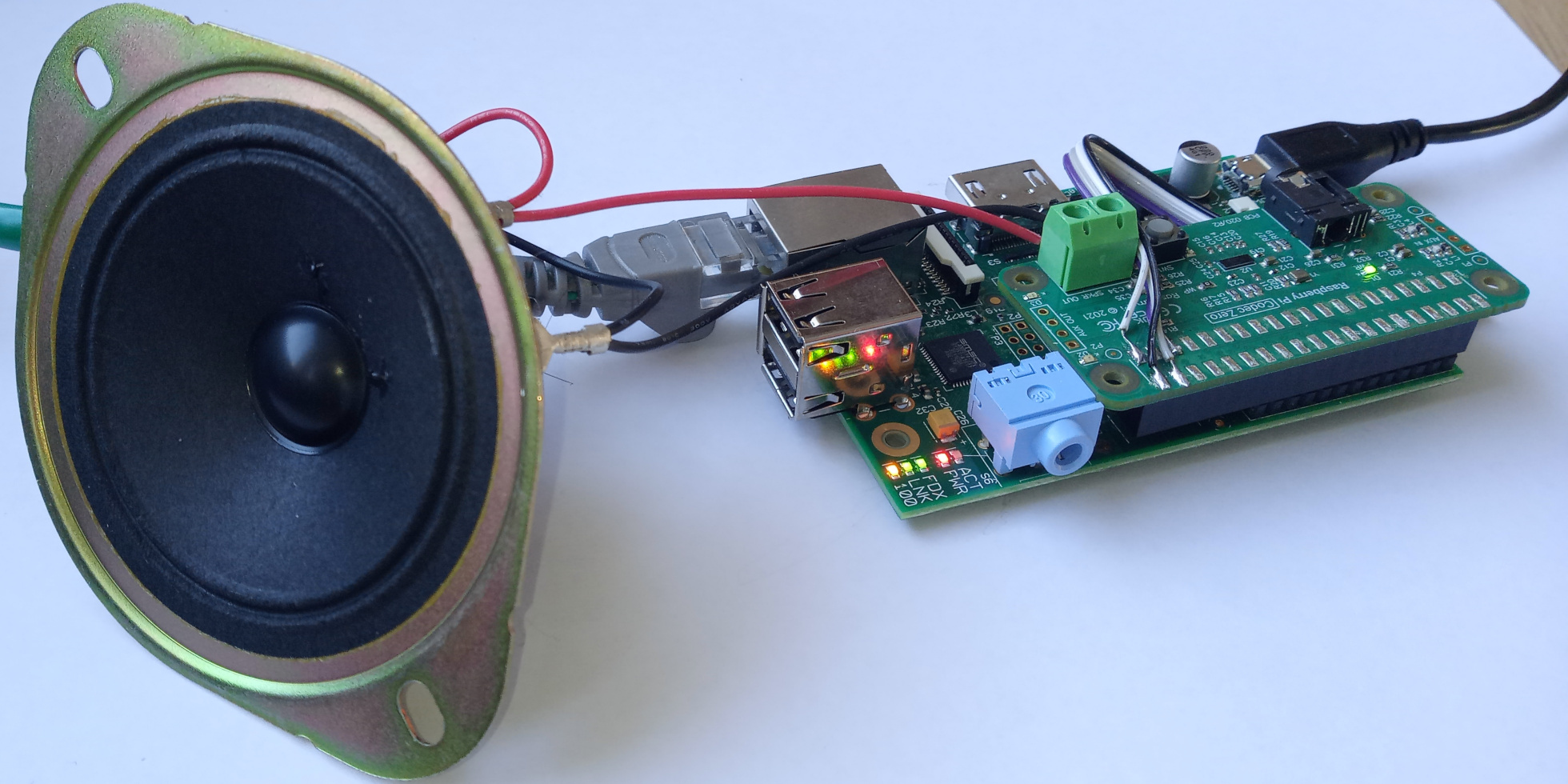
After fixing the mixer settings and connecting a small speaker to the screw terminals, I could hear beautiful music.
Great! My soldering trick works. And my old RPi is useful again after all this time.
The kernel still logs one "I2S SYNC error" each time playback starts on the audio device. This is probably a false alarm. The source code of the audio driver contains the following comment at the place where this error is detected:
  /*
   * Toggle the SYNC flag. After 2 PCM clock cycles it can be read back
   * FIXME: This does not seem to work for slave mode!
   */
Mixer settings
The DA7212 chip on the Codec Zero is a pretty powerful audio codec. It can simultaneously play and record audio. Signals can be recorded through various input channels and played through various output channels. All channels have separate gain settings. These features are controlled via a large number of internal switches and settings in the chip.
The switches and settings in the DA7212 show up on the RPi as mixer controls. The ALSA driver for the Codec Zero reports 99 mixer controls (or 106 controls, if you count certain switches separately). The mixer can be controlled with the ALSA tools on the RPi:
- The program
amixerprovides access to the mixer controls from the command-line. - The program
alsamixerpresents the mixer controls in a text-based interactive user interface.
In my opinion, there are so many controls that alsamixer doesn't provide a useful visual overview.
I simply lose my way in an nearly endless list of controls.
For this reason, I prefer amixer.
It took me some time to figure out how to use the mixer. The documentation of the Codec Zero does not really explain how the mixer works. A whole bunch of mixer controls must be set correctly in order to get any signal in or out of the Codec Zero at all. To figure out the meaning of the mixer settings, I studied the datasheet of the DA7212.
Below, I will summarize my understanding of the most important settings. I hope this helps others to get their Codec Zero playing.
Controls for playing audio:
- Mixer controls "DAC Left Source MUX" and "DAC Right Source MUX" select a digital input stream for the DAC. To play audio, these must be set to "DAI Input Left" resp. "DAI Input Right".
- Mixer control "DAC" controls analog output from the DAC. To play audio, it must be switched On and set to a suitable level. A good default level is 0 dB.
- Mixer control "DAC Soft Mute" is a digital mute function and must be Off to play audio.
- Mixer controls "Mixout Left DAC Left" and "Mixout Right DAC Right" are switches that connect the DAC to the output mixer. These must be On to play audio.
- Mixer control "Headphone" controls audio output to the AUX OUT header. To play audio via AUX OUT, it must be switched On and set to a suitable level. A good default level is -6 dB.
- Mixer control "Lineout" controls the audio output signal to the screw terminal. To play audio via the screw terminal, it must be switched On and set to a suitable level. A good default level is -9 dB.
- I don't understand the meaning of mixer controls "AUX Jack" and "HP Jack". I switch them On just to be sure.
Controls for recording audio:
- Mixer control "Aux" controls analog input via the AUX IN header. To record audio via AUX IN, it must be switched On and set to a suitable level. A good default level is -9 dB.
- Mixer control "Mic 1" controls analog input via the microphone jack. To record audio from an external microphone, it must be switched On and set to a suitable level.
- Mixer control "Mic 2" controls analog input from the on-board microphone. To record audio from the on-board microphone, it must be switched On and set to a suitable level. A good default level is 24 dB.
- Mixer controls "Mic 1 Amp Source MUX" and "Mic 2 Amp Source MUX" select input modes for the microphone signals. These must be set to "Differential".
- Mixer controls "Mixin Left Aux Left" and "Mixin Right Aux Right" are switches that connect the AUX IN signal to the input mixer. These must be switched On to record via the AUX IN header.
- Mixer controls "Mixin Left Mic 1" and "Mixin Right Mic 1" are switches that connect the microphone jack to the input mixer. These must be switched On to record from an external microphone.
- Mixer controls "Mixin Left Mic 2" and "Mixin Right Mic 2" are switches that connect the on-board microphone to the input mixer. These must be switched On to record from the on-board microphone.
- Mixer control "Mixin PGA" controls the output signal from the input mixer. To record audio, it must be switched On and set to a suitable level. A good default level is 6 dB.
- Mixer control "ADC" controls the analog input to the ADC. To record audio, it must be switched On and set to a suitable level. A good default level is 0 dB.
- Mixer controls "DAI Left Source MUX" and "DAI Right Source MUX" select a digital input stream to send to the RPi. To record audio, these must be set to "ADC Left" resp. "ADC Right".
- I don't understand the meaning of mixer controls "AUX Jack", "MIC Jack" and "Onboard MIC". I switch them On just to be sure.