Every Arduino has an on-board clock source, typically running at 8 MHz or 16 MHz. Most Arduinos use a quartz crystal to generate the clock signal, but some models have a ceramic resonator instead.
There seems to be general agreement that ceramic resonators are not as good as crystals [1][2][3]. Some people even warn that ceramic resonators cause problems with high-speed serial communication, but others dispute that. Perhaps a measurement will shine some light on the situation.
I measured the frequency of an Arduino Duemilanove with crystal resonator and the frequency of an Arduino Pro Mini with ceramic resonator. The short story is that the crystal is indeed much more accurate than the ceramic resonator, although the accuracy of the ceramic resonator is sufficient for most applications including serial communication. The long story is written below.
Test setup
Ingredients:
- Arduino Duemilanove with ATmega328 and 16 MHz crystal resonator
- Arduino Pro Mini 5V with ATmega328 and 16 MHz ceramic resonator
- Adafruit GPS shield [4]
- EM-406A GPS receiver
The GPS shield is installed on the Duemilanove, with the PPS (pulse per second) output of the GPS receiver connected to input pins on both Arduinos. The input capture feature of the ATmega328 is used to read the value of 16 MHz counters on both Arduinos exactly once per second. In addition, the internal temperature sensor of the ATmega is read once per second.
Arduino sketch available here: arduinofreq.pde
Unfortunately, GPS reception through my window is not very good. There are periods where fewer than 4 satellites are visible. The GPS receiver needs at least 4 satellites to make an accurate time calculation, otherwise its PPS signal slowly drifts away from the exact time. This has been solved by removing measurements with less than 4 satellites from the dataset before analysis.
Note that I measured only one crystal and only one ceramic resonator. This is a serious limitation which makes it hard to draw general conclusions. It is possible, for example, that my crystal is much more accurate than most crystals. A proper experiment would measure multiple boards from different batches, but I don't have time for such games. Let's just hope that my Arduinos are somewhere in the typical range.
Frequency mismatch
Oscillators are never exactly 16 MHz. Each component has its own small frequency mismatch. It turns out that my crystal is 0.011% faster than 16 MHz, while my ceramic resonator is 0.077% slower than 16 MHz.
Neither oscillator is good enough to build an alarm clock. A clock designed to run at exactly 16 MHz would gain 9 seconds per day with the crystal oscillator, or lose 67 seconds per day with the ceramic oscillator. The accuracy could be improved by measuring the actual frequency of the oscillator and calibrating the Arduino program for that frequency instead of 16 MHz. This effectively eliminates the static frequency mismatch.
Both oscillators are easily good enough for serial communication. An RS-232 style serial link typically allows at least 1% baudrate mismatch. By that standard, the ceramic resonator is still a factor 10 better than needed.
| Arduino model | Duemilanove ATmega328 | Pro Mini 5V ATmega328 |
|---|---|---|
| Clock source | 16 MHz crystal | 16 MHz ceramic resonator |
| Measurement duration | 18 hours | |
| Frequency range | 16001672 ... 16001677 Hz | 15987746 ... 15987918 Hz |
| Mean frequency | 16001674.7 Hz | 15987821.8 Hz |
| Mismatch from 16 MHz | +105 ppm | −761 ppm |
| Standard deviation | 0.7 Hz rms | 43.9 Hz rms |
| AVR temperature | 70 ... 73 °C | 65 ... 67 °C |
Frequency stability
The frequency of an oscillator is not precisely constant; it changes all the time. Frequency variations are partly caused by external factors such as temperature, and partly by inherent noise inside the oscillator.
The standard deviation of the frequency is a first indication of stability. The crystal is quite stable with a standard deviation of only 0.7 Hz, while the ceramic resonator is much more variable.
The stability of a clock depends on the length of time over which it is measured. For example, atomic clocks are extremely stable over periods of days and weeks, but crystals are more stable than atomic clocks over very short periods. The Allan deviation is a common way to express clock stability at different measurement durations.[5][6]
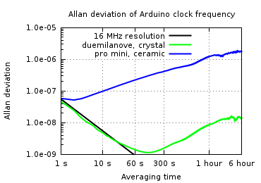 |
The Allan deviation plot above shows that the crystal is much more stable than the resonator. I should point out that this Allan plot is not really up to standards. The initial downward slope of the Duemilanove is purely driven by the limited resolution of my measurement. The upward slopes of both lines are probably caused by temperature variation during the measurement. Under ideal conditions, typical crystal oscillators are much more accurate than what I show here.
Temperature sensitivity
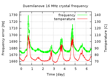
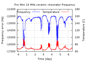
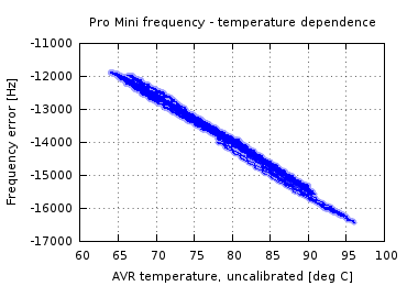
The frequency of an oscillator changes with temperature. I measured the oscillator frequency and the internal temperature of the AVR for several days. Because the resonator is close to the AVR on the Arduino boards, I assume that they go through approximately the same temperature variations.
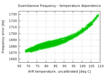
The result shows a strong relation between temperature and frequency. The crystal on my Duemilanove shifts almost 1 Hz per degree Celcius, while the ceramic resonator on the Pro Mini is about 100 times more sensitive to temperature.
 |
 |
 |
 |
| Arduino model | Duemilanove ATmega328 | Pro Mini 5V ATmega328 |
|---|---|---|
| Clock source | 16 MHz crystal | 16 MHz ceramic resonator |
| Measurement duration | 158 hours | |
| Frequency range | 16001671 ... 16001730 Hz | 15983561 ... 15988135 Hz |
| Mean frequency | 16001679 Hz | 15987508 Hz |
| Standard devitation | 7.4 Hz rms | 720 Hz rms |
| AVR temperature | 68 ... 110 °C | 64 ... 96 °C |
| Temperature coefficient | +0.97 Hz / °C | −139 Hz / °C |
| Temperature fit residue | 2.4 Hz rms | 91.4 Hz rms |
Sensitivity to supply voltage
Most oscillators are sensitive to changes in supply voltage. The supply voltage of digital boards such as the Arduino is not always very stable, especially when variable amounts of current are used.
To test voltage sensitivity, I programmed both Arduinos to switch a digital output pin once per second in a random pattern. When switched on, the output pin sends a current of ~ 30 mA into a 120Ω resistor. The extra current causes the 5V supply voltage on the Arduino to drop by ~ 50 mV. If the oscillator is sensative to voltage variation, its frequency will change depending on the on/off state of the digital output.
The supply voltage coefficient is determined by correlating the on/off state of the output pin to the frequency measurements. The Duemilanove crystal frequency drops 1.6 Hz on average when the output pin is enabled. Again, the Pro Mini ceramic resonator is much more sensitive.
| Arduino model | Duemilanove ATmega328 | Pro Mini 5V ATmega328 |
|---|---|---|
| Clock source | 16 MHz crystal | 16 MHz ceramic resonator |
| Measurement duration | 33 hours | |
| Frequency range | 16001672 ... 16001709 Hz | 15984765 ... 15988044 Hz |
| Mean frequency | 16001680 Hz | 15987434 Hz |
| Variable output current | 33 mA pp | 34 mA pp |
| 5V supply voltage variation | 50 mV pp | 30 mV pp |
| Frequency variation correlated with output current |
−1.6 Hz | −76.2 Hz |
| Supply voltage coefficient | +0.03 Hz / mV | +2.5 Hz / mV |
Conclusions
(Note that these conclusions are based on a very limited test with just one crystal and one ceramic resonator.)
- The crystal oscillator on the Duemilanove is much more accurate than the ceramic resonator on the Pro Mini.
- Both oscillators are accurate enough for most applications, including high-speed serial communication.
- Neither oscillator is good enough to use in an alarm clock without calibration. The crystal oscillator may be good enough if the Arduino program is calibrated to compensate the frequency mismatch of the particular crystal on which it runs. The ceramic oscillator will still not be good enough even after calibration.
- Arduinos get hot in direct sunlight.
References
- [1] Ladyada, Arduino UNO FAQ
- [2] Crystal uses (compared to ceramic resonators)
- [3] Recommendations for next iteration of Arduino
- [4] Ladyada, GPS shield
- [5] W.J. Riley, Handbook of Frequency Stability Analysis, NIST, 2008.
- [6] John Ackermann, Frequency stability and accuracy in the real world
- [7] Tom Dunigan, Frequency offset measurements of various clock sources
Contact
Comments, suggestions, corrections are welcome at joris (a) jorisvr.nl
